Database Design: From Novice to Professional [Ch.2: Guided Tour of the Development Process]


![Database Design: From Novice to Professional [Ch.2: Guided Tour of the Development Process]](https://cdn.hashnode.com/res/hashnode/image/upload/v1658828726412/hKQtW3xQ-.jpg?w=1600&h=840&fit=crop&crop=entropy&auto=compress,format&format=webp)
In the previous chapter we talked about how bad design can lead to problems in the future in the two incoming chapters we will talk about the process you can follow that may help you in designing your database.
before we start we need to know that fundamental data items (names, amounts, dates) that you keep for a problem will change very little over a long time. The values will of course be constantly changing but not the fact that we are keeping values for names, amounts, and dates.
Now think about what you do with these pieces of data is likely to change quite often. Designing a database to reflect the type of data involved, rather than what you currently think is the main use for the data, will be more advantageous in the long term.
In this chapter, we take a quick tour of how we will approach the process from initial problem statement, through an abstract model, to the final implementation of a useful application
Thinking processes
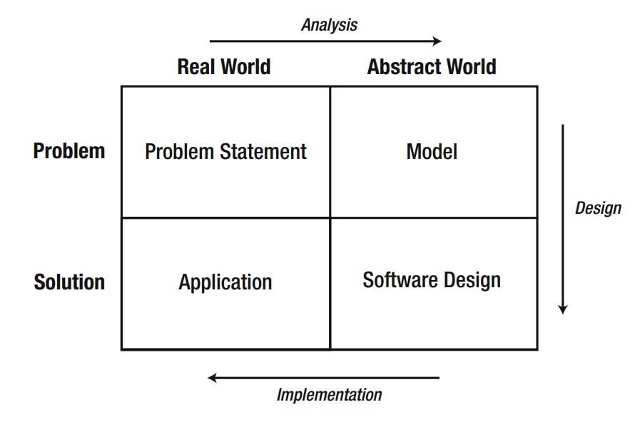
Using this image as a way of thinking about software processes, we will now look at
how the various steps relate to setting up a database project by applying those steps to
one of our old examples "The Plant Database."

Initial Problem Statement
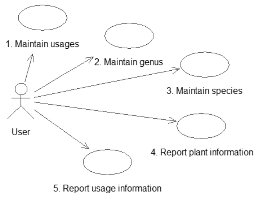
We start with some initial description of the problem. One way to represent a description is with use cases, which are part of UML
Use cases are descriptions of how different types of users (more formally known as actors) might interact with the system
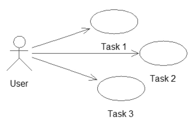
The UML notation for use cases involves stick figures representing, in our case, a type of user, and ovals representing each of the tasks that the user needs to be able to carry out
However, those stick figures and ovals aren’t really enough to describe a given interaction with a system. When writing a use case, along with a diagram you should create a text document describing in more detail what the use case entails
Let’s see how use cases can be applied to our problem from chapter 1
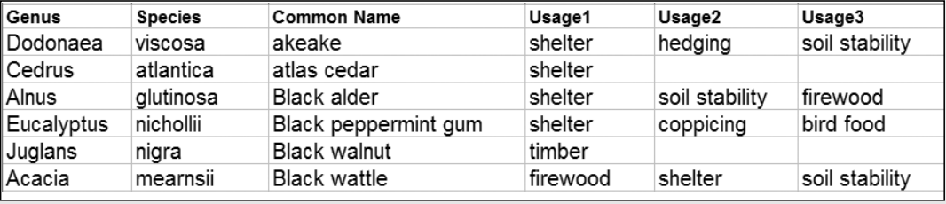
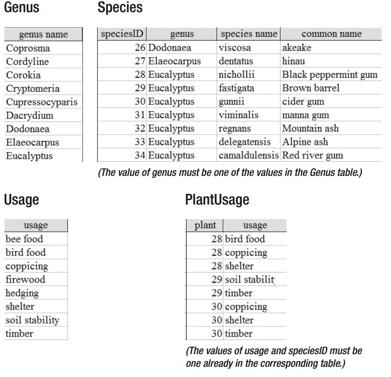
If we consider what typical people might want to do with the data shown, the use cases suggested here would be a start
Use case 1: Enter (or edit) all the data we have about each plant, that is, plantID, genus, species, common name, and usages.
Use case 2: Find or report information about a plant (or every plant) and see what it is useful for.
Use case 3: Specify a usage and find the appropriate plants (or report for all usages).
As explained in the previous chapter, if the data is stored as this image, we cannot conveniently satisfy the requirements of all the use cases, However, finding all the plants that satisfy a particular usage is extremely awkward with the data maintained
Analysis and Simple Data Model
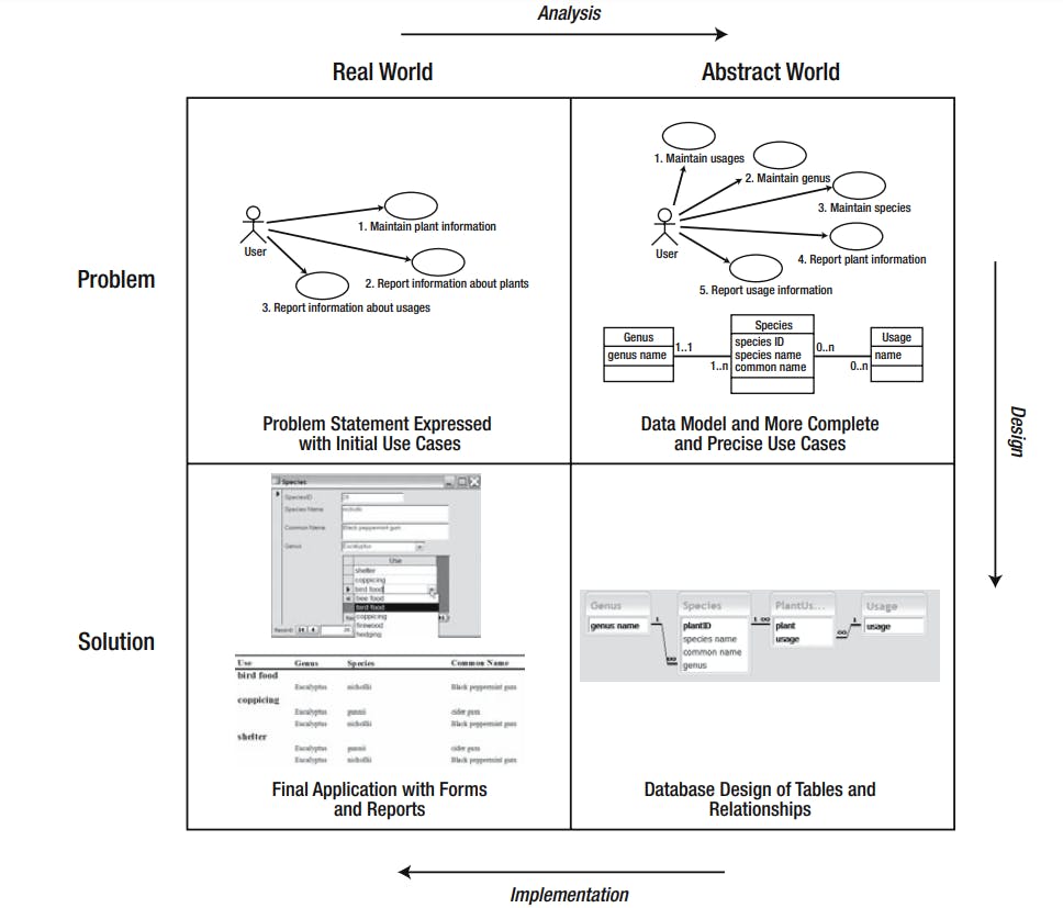
Now that we have an initial idea of where we are heading, we need to become a little abstract and form a model of what the problem is really about(recall first image with the 4 steps we are moving across the top of the diagram)
A practical way to start to get a feel for what the data involves is to sketch an initial data model that is a representation of how the different types of data interact UML provides class diagrams that are a useful way of representing this information.
1) Classes and Objects
Each class can be considered a template for a set of similar things (places, events, or people) about which we want to keep data.
Let’s consider Example "Planet Database" about plants and their usages. An obvious candidate for our first class is the idea of a Plant. Each plant can be described in a similar way in that each has a genus, a species, and a common name and perhaps a plantID number. These pieces of information that we will keep about each plant are referred to as the attributes (or properties) of the class.
The name of the class appears in the top panel, and the middle panel contains the attributes.
There may be processes that a class would be responsible for carrying out. For example, an process for calculating a price including tax. These are known as methods and appear in the bottom panel
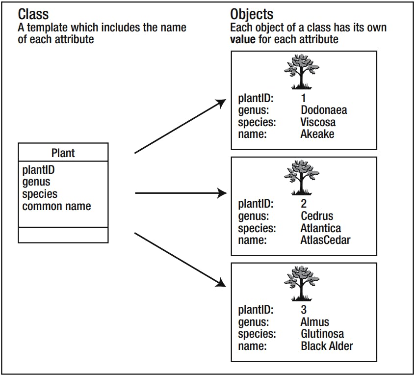
Each individual plant is referred to as an object of the Plant class. The Plant class and some objects
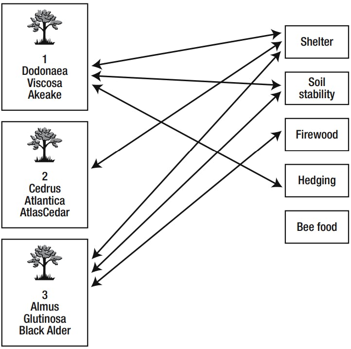
2)Relationship
One particular plant object can have many uses we can see that Akeake can be used for soil stability, hedging, and shelter. We can think of these as a relationship
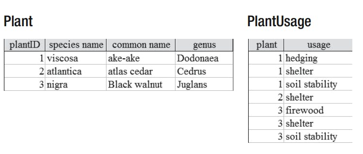
In a database, we would usually create a table for each class, and the information about each object would be recorded as a row in that table as shown. The information about the specific relationship instances would also be recorded in a table. For a relational database, you would expect to find tables to represent the plants and relationship instances shown below.
Cardinality
In UML, a relationship is represented by a line between two class rectangles.
The pair of numbers at each end of the line indicates how many objects of one class can be associated with a particular object of the other class. The first number is the minimum number. This is usually 0 or 1 and is therefore sometimes known as the optionality (i.e., it indicates whether there has to be a related object). The second number is the greatest number of related objects. It is usually 1 or many (denoted *), although other numbers are possible. Collectively, these numbers can be referred to as the cardinality or the multiplicity of the relationship.
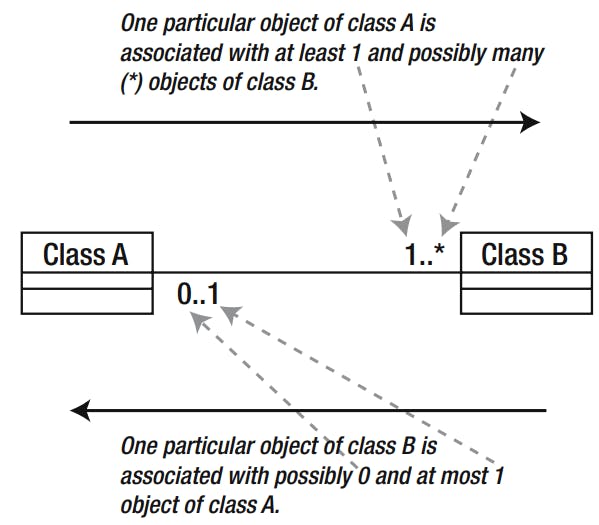
relationships are read in both directions. We can see above that this shows how many objects of the right-hand class can be associated with one particular object of the left-hand class and vice versa. When we want to know how many objects of class B are associated with class A, we look at the numbers nearest class B
We will look at the issue of cardinality further in Chapter 4.
Further Analysis: Revisiting the Use Cases
Using the notation for class diagrams, we can make a first attempt at a data model diagram to represent our plants example. We have a class for both plants and usages, and the relationship between them
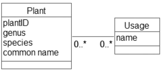
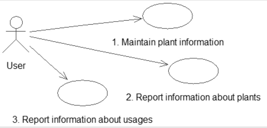
We now need to check whether this model is able to satisfy the requirements of the three use cases
Use case 1: Maintain plant information. We can create objects for each plant and record the attributes we might require now or in the future. We can create usage objects, and we can specify relationship instances between particular plant and usage objects.
Use case 2: Report information about plants. We can take a particular plant object (or each one in turn) and find the values of its attributes. We can then find all the usage objects related to that plant object.
Use case 3: Report information about usages. We can take a particular usage object and find all the plant objects that are related to it
we have a new class, Genus, to add to our data model. Why is it important to include this new class? Well if genus remains as simply an attribute of our original Plant class, we can enter pretty much any value for each object. Two objects with genus Eucalyptus might end up with different spellings (almost certainly if I were doing the data entry). This would cause problems every time we wanted to find or count or report on all Eucalyptus plants.
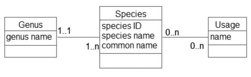
We now have a set of genus objects, and each plant must be associated with exactly one of them. as you see in that we have also renamed the Plant class to Species, as it is the species, or type of plant, that we are keeping information about, not actual physical plants. This opens the way to extend the model later to keep information about actual plants if we so wish
Entering the values of each genus will likely be a separate job from entering data for each species, so it should have its own use case. We don’t want or need to enter a new object for the Eucalyptus genus every time we enter a new species.
But now how does that affect the use cases?
Improving our use cases.
See how the reporting use cases can now be much more precisely defined in terms of the data model.
Use case 1: Maintain usages. Create or update a usage object. Enter (or update) the name.
Use case 2: Maintain genus. Create or update a genus object. Enter the name.
Use case 3: Maintain species. Create a species object. Generate a unique ID, and enter the species and common name. Associate the new species object with one of the existing genus objects and optionally associate it with any number of the existing usages.
Use case 4: Report plant information. For each genus object, write out the name and find all the associated species objects. For each species object, write out the species and common name. Find all the associated usages and write out their names.
Use case 5: Report usage information. For each usage object, write out the name. Find all the associated species objects, and for each, write out the associated genus name, and the species and common name.
Desgin
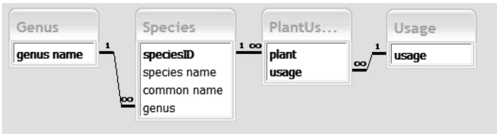
Now each class will be represented by a database table. Because each species can have many usages and vice versa, we need an additional table for that relationship. This is generally the case for relationships having a cardinality of greater than 1 on both ends (known as Many–Many relationships).
Three tables correspond to the classes (Genus, Species, Usage) and the extra table, PlantUsage, gives us somewhere to keep the relationships between plant species and usages The other relationships between the classes can be represented within the database by setting referential integrity between the four tables
Implementation
The first stage in the implementation is to set up these tables and associated relationships and input some data.
We have now implemented our design, but we still need to provide convenient ways to maintain and retrieve the data. This means we have to provide forms and reports that will efficiently satisfy the requirements in our revised set of use cases
End of our design
Remember our first image when we said we go through 4 phases now our trip finished with our example Let's recap that we had 4 phases (Problem Statement, Model, Software Design, Application)
1. Problem Statement:
Express the problem in terms of what a user might want to achieve. For a database problem, this will typically be in terms of the data to be stored and the information that needs to be retrieved. Sketch some initial use cases and a data model.
2. Model:
Undertake an iterative analysis process of reconsidering the data model and the use cases until satisfied you have a complete and precise understanding of the problem. For larger problems, this stage may include making some simplifying or other pragmatic choices.
3. Design:
Choose the type of product to manage the data and create an appropriate design. For a relational database, this will involve designing tables, keys, and foreign keys. Different structures will be required if the project is to be implemented in some other type of product such as a programming language or a spreadsheet. The design phase will be discussed more in next chapters.
4. Application:
Build the application. For a relational database, this will include setting up the tables and relationships and developing forms and reports to satisfy the use cases. Building a web or mobile app that gets data from user and show information.
As now we know a lot of things to consider while designing our database we are ready to move to the next chapter feel free to leave any feedback. Thanks for reading.